|
|||||||


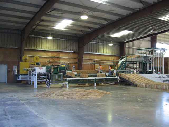
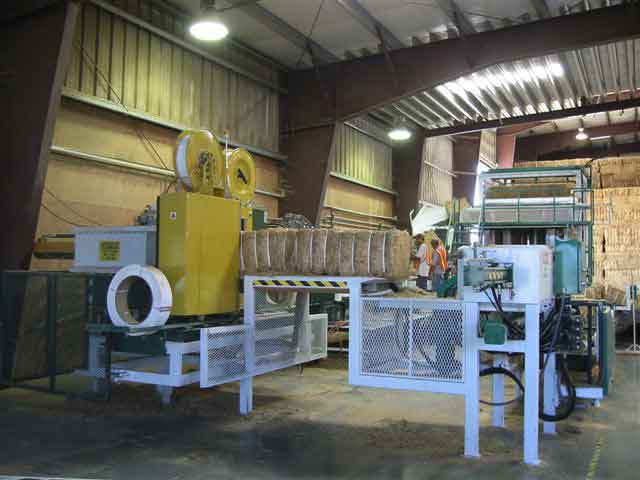
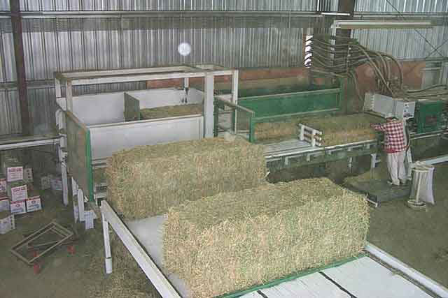
 The process starts with an automated feed table on which the loader operator places the incoming big bales. The machine accepts both 3x3 and 4x3 big bales. This table then advances the big bales into the cutter box which tilts them on their edge to allow for the proper cut. Once the bale has been sliced into sections of 16” x 35”, the bottom slab is slid over, allowing the next slab to fall down behind. These slabs are then pushed forward into the weigh chamber while the operator removes the old twines. Here the simple adjustable beam scale determines the proper amount of hay, which is sectioned off by the feed forks. At this time, the weighed slab is split and advanced onto the lift table.
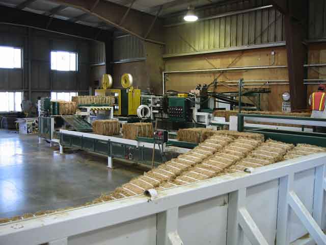
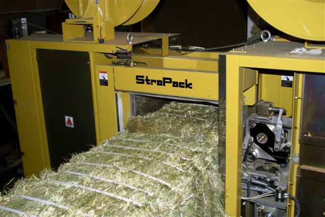
The lift table then raises the slab into the actual compression chamber. The main compression ram now applies pressure against the slab reducing its length to either 24” or 18” depending on the selection made for the finished bale length. Once compressed, the eject cylinder forces the bale horizontally into the banding chamber. The bale is held with two steel plates, while the banding unit places bands transversely along its width. The number of bands is selectable, but normally would be six.
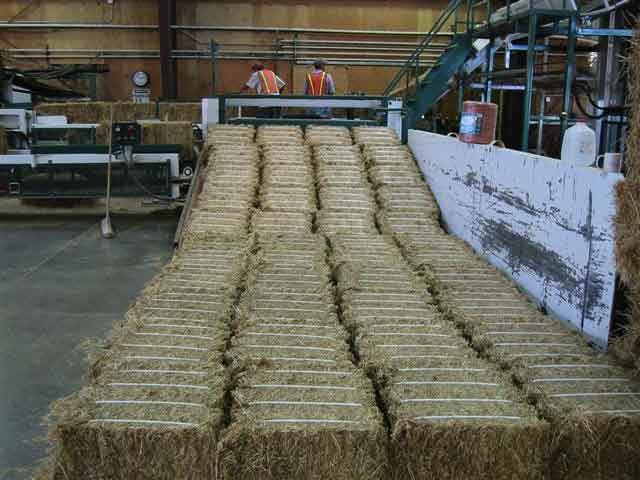
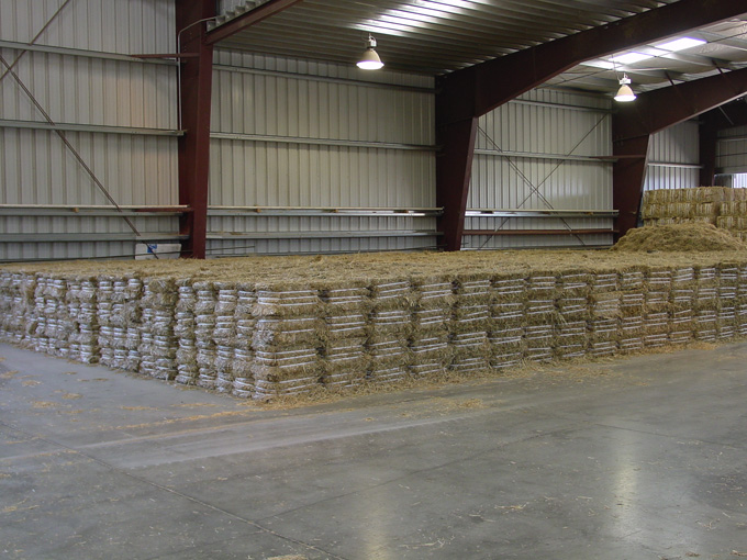
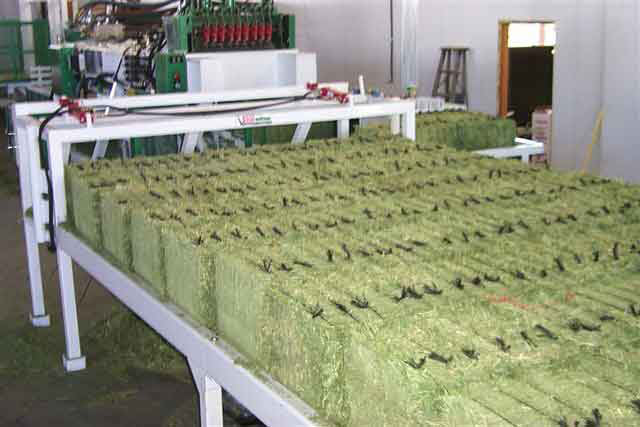
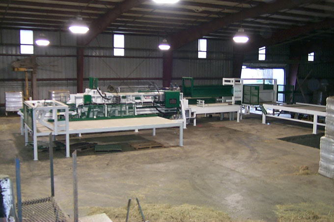
Once this process is complete, the next bale extrudes the finished banded bale out and it expands to its finished length of 24” or 30”, depending on the selection, then is fed into the secondary cutting box. This cutter slices the bales from one 16” x 36” into two 16” x 18” bales. After slicing, the bales are fed into the accumulation stacking table which groups them into proper configurations for mechanically handling into storage or onto a trailer. The entire process happens in approximately 30 seconds with the standard machine, or 15 seconds with the higher power option.
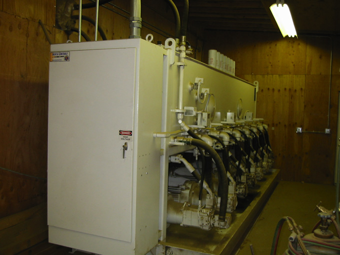
The power for this operation comes from an electric driven hydraulic power station consisting of multiple 30 hp motors, each driving hydraulic pumps. The automation is controlled by a PLC (programmable logic controller), with full operator manual overrides. All manual functions are protected by the PLC to prevent operator damage. All necessary guarding is supplied and safety shutdowns and lockout systems are integrated via the PLC.